Myths around load capacitance – how to choose the right capacitors
关于负载电容的误区 – 如何选择合适的电容器
The load capacitance in the oscillation circuit is one of the most important values for guaranteeing the precision of a quartz crystal. Nevertheless, at the same time it is one of the most common causes of error during the design of an oscillation circuit. There are a number of misconceptions about load capacitance, which we want to clarify today. In addition to that, we will show you how to choose the right capacitors for your circuit.
振荡电路中的负载电容是保证石英晶体精度的最重要数值之一。然而它也是振荡电路设计过程中最常见的错误原因之一。由于“晶振负载电容”这个概念导致诸多误解,今天我们需要特此澄清一下。除此之外,我们还将解释如何选择合适的电容器。
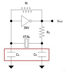
Most quartz crystals are used in a Pierce oscillation circuit . Therefore, two external capacitors are needed. Now the question may arise, how to choose the correct values for those two capacitors?
大多数石英晶体用于皮尔斯振荡电路。因此,需要两个外部电容器。现在问题来了,如何为这两个电容器选择正确的值?

皮尔斯振荡器电路(Pierce Oscillator Circuit)
The first common misconception is that the load capacitance on the crystal datasheet directly identifies the required values for the two capacitors. This means that if the load capacitance of a crystal is 20 pF, both capacitors would need to be 20 pF. However, this is not correct and this would cause frequency shifts.
第一个常见的误解是,晶体数据表上的负载电容直接标识了两个电容器所需的值。这意味着,如果晶体的负载电容为20 pF,则两个电容都需要为20 pF。但是,这是不正确的,因为这会导致频偏。
Another misconception is that the load capacitance on the crystal datasheet needs to be equal to the sum of both capacitors. If we use the same example with a 20 pF crystal, this means that both capacitors would need to be 10 pF each. However, this is also not correct. You could have been lucky with your circuit and everything could have worked properly until now. In most of the cases, the crystal will work in the circuit even with the wrong load capacitance, however the frequency will shift and this could cause other issues. Because both above‑mentioned assumptions about the load capacitance are wrong, we will now show you the right way:
另一个误解是,晶体数据表上的负载电容需要等于两个电容器的总和。如果我们使用相同的示例来使用20 pF晶体,这意味着两个电容器都需要每个电容为10 pF。但是,这也是不正确的。你的电路可能很幸运,直到现在一切都可以正常工作。在大多数情况下,即使负载电容错误,晶体也会在电路中工作,但频率会发生变化,这可能会导致其他问题。由于上述关于负载电容的两个假设都是错误的,我们现在将向您展示正确的方法:
For the total load capacitance in the circuit, all capacitances need to be considered. Therefore, not only the two capacitors, but also the input and output capacitance of the microcontroller and all stray capacitances must be taken into account. This all together forms the load capacitance. The biggest problem now is that it is impossible to know or determine the stray capacitance without an actual circuit. Therefore, during the PCB Design you have to just guess the stray capacitance and later recheck with the final circuit if the frequency is within the tolerance. Working in the industry for several decades, we experienced that the typical stray capacitance in Pierce oscillation circuit is between 3 pF to 5 pF. With this in mind you can easily determine the values for the two external capacitors Ca and Cb with this formula:
对于电路中的总负载电容,需要考虑所有电容。因此,不仅要考虑两个电容器,还要考虑微控制器的输入和输出电容以及所有杂散电容。这些共同构成了负载电容。现在最大的问题是,如果没有实际电路,就不可能知道或确定杂散电容。因此,在PCB设计过程中,您只需猜测杂散电容,然后与最终电路重新检查频率是否在容差范围内。在这个行业工作了几十年,我们根据经验得出:皮尔斯振荡电路中的典型杂散电容在3 pF至5 pF之间。考虑到这一点,您可以根据负载电容计算公式来轻松确定两个外部电容器 Ca和 Cb的取值。

负载电容计算公式(Load Capacitance)
Another recommendation is to select Ca and Cb to have similar values, or at least not far away from each other. This will prevent unexpected frequency shifts and other interference. If Ca and Cb should not be equal, then Ca should be smaller than Cb.
另一个建议是选择具有相似值的 Ca和 Cb。在此,晶诺威科技建议这两颗匹配电容等值选取,这将防止意外的频移和其他干扰,以增强晶振工作的稳定性。如果 Ca和 Cb不等值,则建议Ca应小于Cb。
However, because you can only estimate the stray capacitance it is really important to measure the frequency of your actual circuit to recheck if the frequency reaches the required accuracy for your application.
由于您对杂散电容做出的仅是估算值,因此晶诺威科技建议测量实际电路的输出频率,以重新检查频率是否达到应用所需的精度。


