Frequency stability is a significant feature of any given oscillator. A good oscillator must be able to inject constant frequency output under varied load environments.
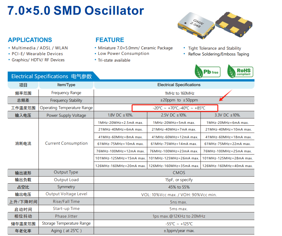
Quartz crystal oscillators have received much attention due to their ability to overcome the electric challenges that have affected the frequency stability of oscillators, including changes to the oscillator’s direct current input power voltage, temperature variations, and load variations.
Oscillation is the repeated variation in current or voltage in a given electrical circuit that results in a periodic waveform. The number of times the cycle is repeated per second gives the oscillation frequency. The electronic device that produces oscillation is known as an oscillator.
Equivalent Model of the Quartz Crystal
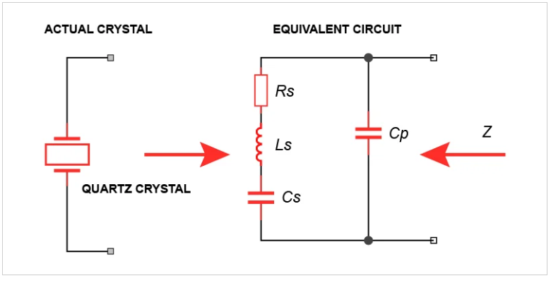
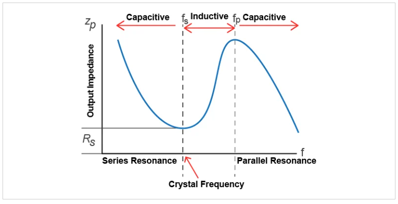
Quartz Crystal Impedance Against Quartz Crystal Frequency
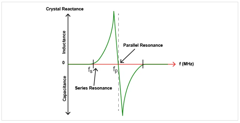
Quartz Crystal Reactance Against Quartz Crystal Frequency
Quartz Crystal Oscillator Configurations
Colpitts Quartz Crystal Oscillator
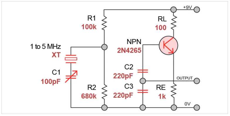
The configuration is designed using a common collector amplifier. The role of resistors R1 and R2 is to set the direct current bias level at the base while the resistor RE sets the level for the output voltage. The resistor R2 should be set as large as possible to serve as a preventive measure to the crystal connected parallel to it.
The connected transistor 2N4265 is an NPN with switching above 100 MHz, higher than the crystal, which ranges between 1 and 5 MHz. From the configuration, capacitors C2 and C1 shunt the transistor output to reduce the amount of feedback signal. Therefore, the capacitor C1 and C2 maximum values are limited by the transistor’s gain. For the avoidance of power dissipation in excess, ensure that you keep the output amplitude low.
CMOS Crystal Oscillator
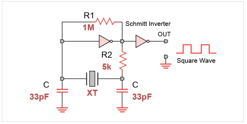
This type of crystal operates through series resonance frequency. Initially, it is biased into its by a feedback resistor R1 in its operating region center. The action will ensure that the Quality factor point of the used inverter is a high gain region. The R1 value is 1 M Ohms. It is important to ensure that the value of R1 is over 1 M Ohm.
The biggest benefit of this type of crystal oscillator is its ability to readjust itself and maintain 360 degrees oscillation phase shift. Unlike the previously discussed oscillators that give a sinusoidal waveform output, this transistor, due to utilization of the digital logic gate, gives a square waveform output that oscillates between low and high. Its operating frequency fluctuates depending on the switching features of the logic gate used.
Pierce Crystal Oscillator
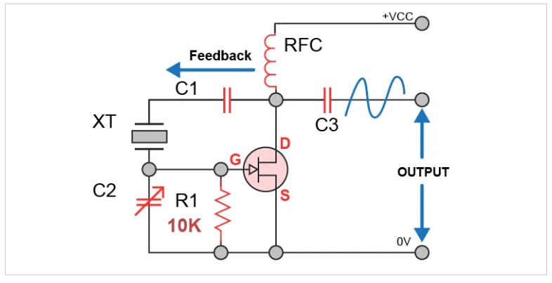
Here, the crystal XT determines the oscillating frequency. Series resonance frequency is the frequency in which it operates. This creates a low impedance between the input and output. The crystal is used in most digital timers, clocks, and watches. In the circuit, R1 is used to control the feedback amount.
Microprocessor Crystal Oscillator
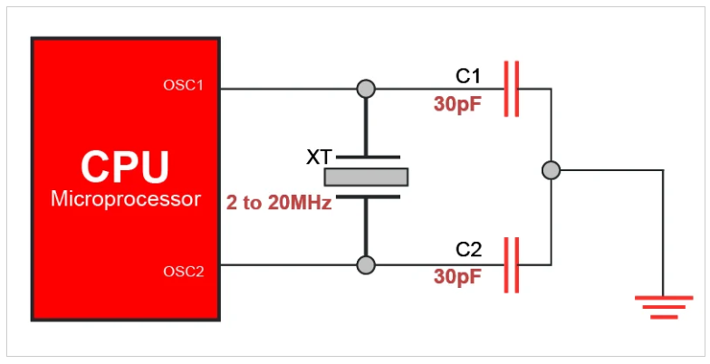
Most microcontrollers and microprocessors have pins labeled OSC1 and OSC2. These are the oscillator pins of the IC used to connect to the quartz crystal that is externally located. Sometimes the pins connect to ceramic resonators and standard RC networks of the oscillator. This type of oscillator produces a square waveform that is continuous. It is applied in system timing and master clocks.
Most microcontrollers and microprocessors have pins labeled OSC1 and OSC2. These are the oscillator pins of the IC used to connect to the quartz crystal that is externally located. Sometimes the pins connect to ceramic resonators and standard RC networks of the oscillator. This type of oscillator produces a square waveform that is continuous. It is applied in system timing and master clocks.


